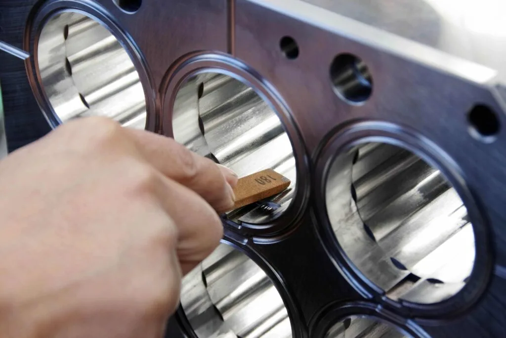
Engineering note: Precision cosmetic tooling, injection molding, secondary finishing, assembly, and functional testing operate as an integrated manufacturing capability chain; specific tool steel selections and Rockwell hardness parameters are engineered and validated per program requirements.
In high-performance luxury beauty manufacturing, precision cosmetic tooling defines the operational boundary between tactile prestige and boundary seal failure. Holding micron-level dimensional tolerances requires synchronizing steel tooling physics with real-time polymer rheology.
Verification Benchmarks: Steel tooling cavities are machined to ±0.005mm in hardened S136 mirror steel (HRC 48–52). Finished as-molded Critical-to-Quality (CTQ) dimensions for airless bottles and closures are validated to ±0.02mm with statistical process capability maintained at CpK ≥ 1.33 via 2.5D optical and CMM measurement.
2.2 Scientific Gate Placement and Dynamic Pack-and-Hold: Eliminating Sink Marks in Heavy-Wall Components
Sink marks are the visible signature of non-scientific processing — localized shrinkage at thick sections that was never compensated at the tooling stage.
- Gate placement: A gate located at the thickest functional section delivers pressure where the material needs it latest, enabling the pack-and-hold phase to suppress sink formation (see ISBM Chiller Profiling & Gate Freeze-Off for the coupled pressure/pack logic).
- Dynamic pack-and-hold: Two-stage injection pressure (fill → pack → hold) with timed transfer points compensates volumetric shrinkage while the gate is still molten; heavy-wall luxury components (2.5–4.5 mm wall sections) are only sink-free when pack-and-hold and cooling are engineered as one system.
- Shrinkage compensation in steel: Cavity dimensions are cut larger than the target part dimension by the polymer’s as-molded shrinkage — for semi-crystalline resins (PP, POM, PETG) this compensation is directional and can exceed 1%·mm/mm. The part is the drawing; the steel is the drawing plus shrinkage math.
3. Where Tolerance Actually Lives: Precision Cosmetic Tooling & Polymer Shrinkage
3.1 Steel Dimensions vs. As-Molded Dimensions: Compensating for Semi-Crystalline Polymer Shrinkage Rates
A common sourcing mistake is quoting part tolerance without distinguishing steel tolerance from as-molded tolerance in precision cosmetic tooling programs.
- Steel tolerance is what the mold maker holds on the cavity block (CNC/EDM, typically ±0.005 mm for precision work).
- As-molded tolerance is what the part measures after shrinkage, warpage, and process spread — always larger, and resin-dependent. Semi-crystalline polymers (PP, POM, PETG, PA) exhibit anisotropic shrinkage; amorphous resins (PMMA, ABS, AS, PC) shrink more uniformly but with different magnitudes.
- The irreducible chain: resin lot variation → drying → melt temperature → mold temperature → pack pressure → cooling time → post-ejection relaxation. Every link adds spread. A shop that controls the chain controls the as-molded band; a shop that only quotes the drawing does not.
3.2 Multi-Cavity Balancing: The Cavity-Butterfly Effect
High-cavity tools (8/16/32 cavities for closures, actuators, and collars) multiply the tolerance problem: each cavity has its own steel, its own cooling, its own flow path.
- Cavity-to-cavity variation is the dominant source of pack spread in volume production (see Multi-Cavity Injection Tooling & Core-Shift Tolerances and Core-Pin Deflection in Deep-Draw Molding).
- Balancing techniques: runner balance (natural, not cut-and-try), gate-size equalization, per-cavity cooling control, and cavity-pressure monitoring convert a 16-cavity tool from 16 independent problems into one repeatable process.
3.3 Dimensional Verification: 2.5D Optical Profile Projectors and Coordinate Measuring Machines (CMM)
Tolerance claims are only as strong as the inspection that proves them:
| Verification Tool | What It Proves | Typical Resolution (Industry) |
|---|---|---|
| CMM (Coordinate Measuring Machine) | 3D datums, bore positions, concentricity | micron-level |
| In-line optical / CCD gauging | 100% dimensional screening in production | 0.1 s per part class |
- CTQ-first inspection: Critical-to-Quality dimensions (seal rims, thread pitch, stem alignment, piston OD) are inspected at higher frequency than non-functional cosmetic boundaries.
- Evidence chain: Demand per-cavity capability studies (not blended averages) and full first-article inspection (FAI) reports tied to resin lots and machine calibration.
4. Technical Sourcing Checklist: What Packaging Engineers Must Demand Beyond 2D Drawings
4.1 Demanding Critical-to-Quality (CTQ) Dimension Capability Studies (CpK Index)
A 2D drawing defines the target; a capability study defines the proof.
| Requirement | What to Demand | Pass/Fail Signal |
|---|---|---|
| Capability index (CpK) | Per-cavity capability studies on CTQ dims from a defined sample plan | CpK ≥ 1.33 (industry standard = ±4σ process) |
| First-Article Inspection (FAI) | Full dimensional FAI tied to drawing rev, resin lot, machine number | Sign-off before pilot release |
| Multi-cavity matrix | Per-cavity mean/range matrix proving cavity balance | Spread within defined band per cavity |
| Ongoing SPC | Control charts (X-bar/R) on CTQ dims during volume runs | No special-cause signals in review window |
4.2 VEQA’s Precision Cosmetic Tooling Feasibility Protocol
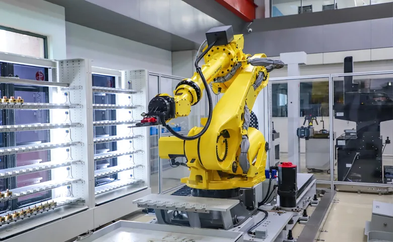
VEQA’s affiliated manufacturing system supports tooling, molding, secondary processing, assembly, and testing as a single capability chain:
- DFM & Moldflow Study: wall-thickness uniformity, gate placement, shrinkage compensation, and sink-risk review before steel is cut.
- Prototype & Tooling Development: SLA/light-curing 3D printing validates geometry and haptics in 48h before cutting production steel.
- Pilot Cavity Qualification: single-cavity validation of CTQ dimensions, as-molded shrinkage confirmation, and aesthetic sign-off.
- Verification Handshake: checked against our recorded 12-laboratory testing capabilities (torque retention, 0.23ml dosing, vacuum decay, and drop shock).
- Volume Release: SPC-monitored mass production across airless bottles and luxury cosmetic jars.
5. Tooling & Mold Engineering FAQ
What is the industry tolerance standard for precision cosmetic packaging molds?
Standard commercial packaging holds ±0.1mm to ±0.2mm, whereas precision luxury cosmetic tooling achieves ±0.02mm on critical-to-quality (CTQ) sealing boundaries and closure threads, using hardened S136 mirror steel and per-cavity optical/CMM inspection (CpK ≥ 1.33).
Why does steel tooling tolerance differ from as-molded part tolerance?
Steel tolerance reflects CNC/EDM machining precision (±0.005mm), whereas as-molded part tolerance accounts for polymer volumetric shrinkage, resin lot variance, thermal contraction, and post-ejection stress relaxation.
How long does a cosmetic packaging DFM and prototype evaluation take?
Comprehensive DFM moldability reviews and CAD/STP file analysis are completed within 24 hours. Rapid 3D physical prototyping takes 48–72 hours, with pilot T1 tooling samples delivered in 25–35 days.
Engineering Feasibility Review
Request a Precision Cosmetic Tooling Assessment
Need DFM (Design for Manufacturing) validation on your bespoke cosmetic packaging drawings? Submit your 3D STP/CAD files for engineering feedback within 24 hours.